UniFi Relay - Switching high powered loads - How to guide
Learn how to switch high-powered loads safely with UniFi Relay, including wiring, part selection and setup guidance in this step-by-step how-to guide.
The Ubiquiti UniFi Protect Smart Relay (USL-Relay) is a fine piece of kit for pulling physical infrastructure into your UniFi ecosystem. It has one hard limit: 10 amps per port. Here is how to use it to switch a 63 A EV charger, a 100 A commercial heater, or a whole building from grid to generator — without destroying it. Parts and wiring are covered for both UK and US installations.
Bridging smart tech and heavy iron
Contactor
For on/off control of a single heavy load.
Automatic transfer switch
For moving one load between two power sources.
1. The contactor (for on/off control)
A contactor is essentially a heavy-duty industrial relay. It consists of two entirely separate electrical circuits:
- The coil (low power) — an electromagnet that needs very little current, under 1 A, to activate.
- The main contacts (high power) — heavy metal lugs designed to handle 63 A or 100 A loads.
Instead of switching your appliance directly, the USL-Relay acts as the trigger. When you press On in the UniFi app, the relay sends a small signal to the contactor's coil. The coil magnetises and loudly slams the heavy main contacts shut, allowing the full current to flow to your appliance.
2. The automatic transfer switch (for changing power sources)
If you want to use the UniFi app to switch a single load between two different power sources — swapping a building from grid to generator, say — you cannot simply use two standard contactors. If a software glitch or a mechanical fault causes both contactors to close at the same time, the grid and the generator will violently collide and cause a catastrophic short circuit.
You need a device with a mechanical interlock. The most cost-effective way to get one is a motorised automatic transfer switch (ATS). It takes two massive inputs, Source A and Source B, and provides one output. Its internal motor physically throws a heavy switch block left or right, so it is mechanically impossible for both sources to be connected at the same time.
The relay never carries the load. It only tells something much bigger what to do.
Scenario A — simple on/off with a contactor
First, the relay needs its own DC supply
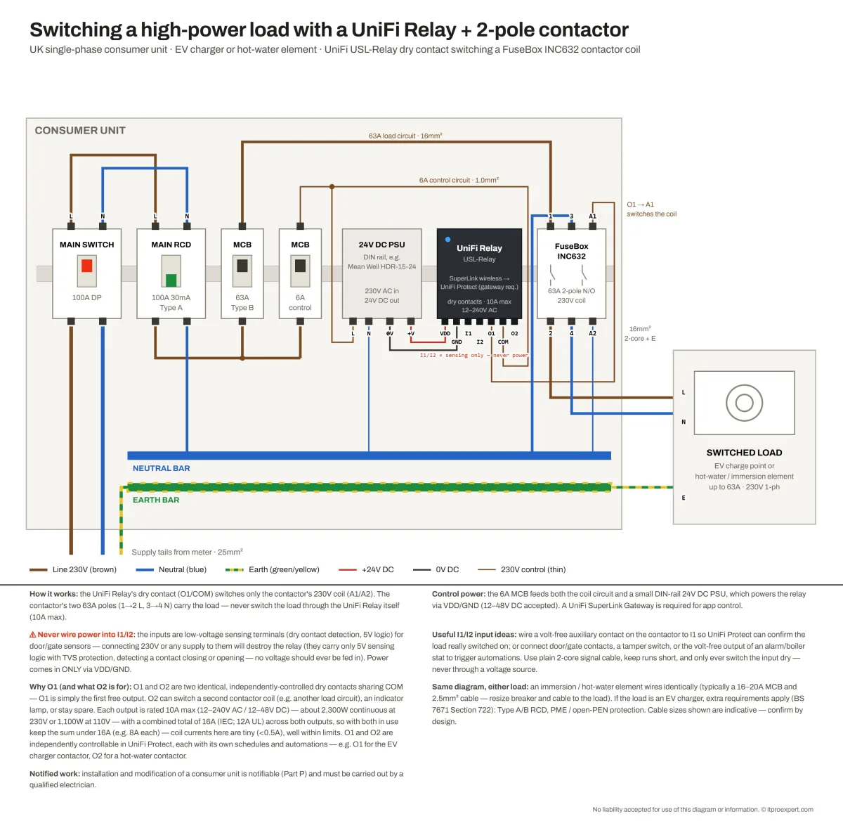
This is the step people miss. The USL-Relay is not mains powered — it takes 12–48 V DC into its VDD and GND terminals. In a consumer unit the tidy answer is a small DIN-rail 24 V DC power supply, a Mean Well HDR-15-24 or similar, 230 V AC in and 24 V DC out, fed from the same 6 A control MCB that feeds the coil circuit.
The relay's outputs are entirely separate from its own power. O1 and COM are a volt-free dry contact, which is exactly why a relay running on 24 V DC can switch a 230 V coil circuit.
The low-voltage control circuit (the coil)
Buy a contactor with a 230 V AC coil, meaning the electromagnet triggers on standard mains voltage.
Power the relay
Feed the DIN-rail 24 V DC PSU from a dedicated low-amp breaker — 6 A is plenty — and run its output into VDD and GND on the relay.
Feed the contact
Run a 230 V live from the same 6 A breaker into the COM terminal of the relay.
Relay to coil
Run a wire out of O1 and connect it to the A1 terminal on the contactor.
Neutral to coil
Connect a standard neutral wire directly to the A2 terminal on the contactor.
Close the circuit
When the relay closes its dry contact, 230 V flows from COM through O1 into A1, powering the electromagnet and completing the circuit at A2.
Scroll the diagram sideways →
The high-voltage load circuit — 2-pole or 4-pole
The main power feed for your heavy appliance does not touch the UniFi relay at all. It goes strictly through the contactor's main lugs, labelled 1/L1, 3/L2 and so on, and out through 2/T1, 4/T2.
Single-phase 230 V (UK)
You only need a 2-pole contactor. Connect your live feed to L1 (top) and the output to the appliance from T1 (bottom). Connect your neutral feed to L2 (top) and the output from T2 (bottom).
Three-phase
You need a 4-pole contactor. Wire Line 1 (brown), Line 2 (black), Line 3 (grey) and neutral (blue) sequentially through the four poles.
North American variant — 120/240 V split-phase
The control principle is identical, but four things change on a US installation:
- Coil voltage. Specify a 120 V AC coil, not 230 V, and feed the relay from a dedicated 15 A or 20 A branch circuit.
- Which conductors get switched. A 240 V load is fed by two hot legs. Both hots go through the two poles; the neutral is not switched and runs straight through to the load.
- Form factor. US installations use definite purpose (DP) contactors rather than DIN-rail modular units, and they step in 30/40/50/60/75/90 A ratings — a 60 A DP contactor is the practical equivalent of the UK 63 A part.
- Terminal markings. DP contactors label the main lugs L1/T1 and L2/T2. The coil terminals are often unmarked quick-connect spades rather than A1/A2, so check the datasheet before you land the control wires.
Scroll the diagram sideways →
Sizing, and the extra rules for EV chargers
Cable and breaker sizing follows the load, not the relay. As an indication for a 63 A single-phase load: 16 mm² on the load circuit, 1.0 mm² on the 6 A control circuit, and 25 mm² supply tails. An immersion or hot-water element wires identically on a smaller circuit — typically a 16–20 A MCB and 2.5 mm² cable. These are starting points only; resize the breaker and cable to the actual load and confirm by design.
Working out your output budget: O1 and O2
O1 and O2 are two identical, independently controlled dry contacts sharing a common COM. O1 is simply the first free output — there is nothing special about it. Each is rated 10 A maximum at 12–240 V AC or 12–48 V DC, roughly 2,300 W continuous at 230 V or 1,100 W at 110 V.
The combined figure is the one to watch. With both outputs in use, keep the sum under 16 A — 8 A each, for example. Switching contactor coils you are nowhere near that, since coil currents here are tiny. Both outputs are independently controllable in UniFi Protect, each with its own schedules and automations, so a single relay will happily run O1 for an EV charger contactor and O2 for a hot-water contactor.
Useful things to do with I1 and I2
The sensing inputs are easy to overlook, and they close a real gap: they let Protect know what actually happened rather than only what it asked for.
- Wire a volt-free auxiliary contact on the contactor to I1, so Protect can confirm the load really switched on — not just that the command was sent.
- Connect door or gate contacts, a tamper switch, or the volt-free output of an alarm panel or boiler stat to trigger automations.
- Use plain 2-core signal cable, keep the runs short, and only ever switch the input dry — never through a voltage source.
Scenario B — switching sources with an ATS
An ATS normally switches on its own when it senses a power cut. We can use the UniFi relay to trick it into switching exactly when you press the button in the UniFi app.
An ATS has main high-voltage lugs for the primary (grid), the backup (generator) and the output. It also has small, low-voltage sensing terminals, usually labelled AR/AN for primary sensing and BR/BN for backup sensing.
Wire the heavy cables
Run the grid and generator power cables to the main lugs as normal, and the output to the building or load.
Intercept the sensing live
Instead of wiring the grid's sensing live wire directly into the AR terminal, run it through the O1 terminals on your UniFi relay first.
On means grid
When you turn the UniFi app on, the sensing circuit completes. The ATS motor senses the grid and physically throws the massive switch to the grid input.
Off means generator
When you turn the app off, the relay breaks the sensing wire. The ATS suddenly thinks the grid has died, and its internal motor draws power from the backup side to loudly slam the switch over to the generator input.
Scroll the diagram sideways →
North American variant — drive the remote test input instead
The sensing-line trick works on the generic dual-power changeover units, but it is the wrong approach for listed US transfer equipment. A UL 1008 transfer switch is built around a generator controller with 2-wire start, so faking a utility failure fights the controller rather than co-operating with it.
Use the terminals the manufacturer already provides. The ASCO Series 185 controller, for example, includes terminal provisions for a remote test switch — which is exactly the job the USL-Relay's dry contact is suited to: close the contact to command a transfer, open it to return to utility. No high-voltage sensing wire passes through the relay at all, and the switch keeps its listing.
Recommended parts — United Kingdom
Unless noted otherwise, these mount on a standard DIN rail enclosure and use 230 V AC coils or motors compatible with the USL-Relay.
63 A contactors — on/off
For loads up to 63 amps: standard EV chargers and sub-mains.
FuseBox 63A 2 Pole Contactor (INC632)
TLC Direct
~£16.68 inc VAT
Europa 4 Pole Modular Contactor 63A (EUC3-63-4P)
CPC
~£45.46 ex VAT
Generic Modular Contactor 4 Pole 63A
Excel Shop
~£48.00
100 A contactors — on/off
For extreme loads up to 100 amps: commercial heating arrays and whole-panel switching.
WCED 2 Pole 100A (WAC2P100)
UK EV Installers
~£25.10 inc VAT
Power & Data UK 4 Pole Modular Contactor 100A (WAC4P100)
Power & Data UK
~£40.45
100 A / 125 A automatic transfer switches — source swapping
For safely switching a whole building or heavy load between grid and generator. Build quality and transfer speed vary enormously in this category, and it is the one place in this guide where the cheapest option is a false economy.
Chint NZ7 series, e.g. NZ7-125H/4/100 (100 A, 4-pole)
Chint is a major global switchgear manufacturer. The NZ7 is a CB-class ATS built to IEC/EN 60947-6-1, with motor-driven operation, an integrated digital controller, dual mechanical and electrical interlocking and a 230 V AC control supply. Panel or fixed mounting rather than DIN rail.
Trade price on application
Chint Europe UK, LED Controls and Expert Electrical Supplies. Full range at chint.co.uk.
TOMZN / EARU upgraded modular ATS
The upgraded models — usually grey rather than white or blue — transfer in the millisecond range instead of the base W2R's clunky one-to-two-second delay. Not commercial grade, but a distinct step up in build quality.
~£60 – £80
Base W2R-100 / W2R-125
The unit everyone finds first, and the one to avoid. Slow, clunky changeover and inconsistent reliability. It is popular with off-grid solar DIYers because it is cheap, not because it is good.
~£35 – £45
Europa ATS-CON1002PME 100A 2 Pole Transfer Switch
A fully certified, metal-enclosed British Standard install. This is what an inspector wants to see on anything that genuinely matters.
~£800.00+
Recommended parts — United States
US parts are specified differently: 120 V AC coils, definite purpose contactors instead of DIN-rail modular units, and UL listing rather than BS EN marking. Prices below are typical street prices and move around; treat them as a guide and confirm with your wholesaler.
40–60 A contactors — on/off
For EV chargers and heavy 240 V appliances. A 60 A DP contactor is the practical equivalent of the UK 63 A part.
Square D 8910DPA62V02, 60 A 2-pole
120 V AC coil, quick-connect terminals, metal base plate. Electrical wholesalers and IMC Direct.
Wholesaler pricing
ABB DP60C2P-1, 60 A 2-pole
120 V AC coil, non-reversing, one normally open and one normally closed auxiliary. Amazon and wholesalers.
Wholesaler pricing
Shopcorp 60 A 2-pole definite purpose contactor
75 A resistive, 120 V AC coil, UL listed under file E508253, DIN rail or panel mount. Contactor Depot.
Budget option
100 A switching — on/off
Definite purpose contactors run out of headroom around 90 A. Above that you move to a lighting contactor or an IEC-frame contactor.
ATO 100 A lighting contactor
110 V or 220 V AC coil, 2-pole and 4-pole versions, rated for 100,000 cycles.
Direct from ATO
Shopcorp 100 A 4-pole IEC contactor
120 V AC coil, DIN rail mount. Contactor Depot.
Budget option
Automatic transfer switches
Read the UL 1008 warning above before you choose. The first option is cheap and unlisted; the other two are listed and will pass inspection.
Generic 2-pole 100 A DIN-rail changeover (TOMZN, JOTTAELE and similar)
110 V versions sold on Amazon and eBay. CE marked, not UL 1008 listed, and the base models transfer slowly. Same caveats as the UK section above.
~$55 – $65
Generac RXSW100A3 / RXSC100A3, 100 A single-phase
120/240 V, NEMA 3R aluminium enclosure, integrated load management for four HVAC loads. Lowe's and Generac dealers.
Dealer pricing
ASCO Series 185, 100 A – 400 A
Listed to UL 1008, true double-throw contacts with inherent mechanical interlocking, and terminal provisions for a remote test switch.
From ~$1,600
Planning a UniFi-integrated installation?
We design and support the network and UniFi side; your electrician handles everything beyond the coil. More build notes live in the Ubiquiti Universe.